Bug

Sunday, November 27, 2011
Motor running... sorta
I have my test motor running in simple trapezoidal commutation, next is FOV control.

Friday, November 18, 2011
Electronics work


In order to do this I had to make sure any loose ends were tied up, I found the DC-DC converter didn't have the correct inputs from my electronics. I had to experiment with powering up the DC-DC converter which eventually I got working. It required a +12 feed from the ignition, high voltage input and the last thing is a 12 volt lead acid battery which has to be hooked to the output of the DC-DC converter for it to function.
Tuesday, October 4, 2011
More debugging
So its taken me longer than I thought to debug, I'm having to re-write large portions of the code. One of my problems is I referenced multiple sources for the basis of my code. This led to errors between the various parts. I am now using a single reference.
I'm finally getting real numbers out of my 3 PWM pins for the motor control. This has allowed me to run speed checks using an oscilloscope, the bad news is the total control loop takes 157 microseconds now, it needs to be somewhere around 50-70 microseconds. I discovered that sine/cosine calculations take a long time even on the ARM cpu, so I'm probably going to have to use a lookup table.
This should speed things up a lot and knock off around 100 microseconds from the code.
I'm finally getting real numbers out of my 3 PWM pins for the motor control. This has allowed me to run speed checks using an oscilloscope, the bad news is the total control loop takes 157 microseconds now, it needs to be somewhere around 50-70 microseconds. I discovered that sine/cosine calculations take a long time even on the ARM cpu, so I'm probably going to have to use a lookup table.
This should speed things up a lot and knock off around 100 microseconds from the code.
Tuesday, September 27, 2011
Debugging
I'm still working through debugging everything. I found wiring errors in my control box, some wired to the wrong locations and a couple of missing wires to the deadtime control chip.
Once I got the wiring all fixed I ran some tests, these tested inputs and outputs to make sure they functioned correctly. I also tested all the interrupts in my motor control firmwire, the timed interrupts and the external interrupts.
Motor control uses center or symmetric PWM, this is different from the normal edge aligned PWM and prevents all the outputs switching on simultaneously, it staggers them instead. I had previously written to the authors of the leaflabs compiler and they had given me instructions on how to modify the compiler so it does center aligned PWM. Unfortunately the compiler has been updated a number of times since the end of last year, I dug through the new files and managed to figure out myself how to make the modifications. I confirmed this via a high speed oscilloscope.
I had to understand how the deadtime generator worked for my start routines and regen braking routines to work. I again used a high speed PC based oscilloscope to analyse the signals. It behaves as expected.
One of the biggest headaches I've had and the hardest thing to write is all the different driving states and how the motor knows where it is and where its going. This is everything from standstill, to initial acceleration, switch to closed loop control, regen braking, coasting, and stopping.
I had originally done this via many IF statements inside functions triggered by hall sensor interrupts and a timed 10hz interrupt which handles reading the throttle and enable etc. However it became very difficult to manage and draw out in a block diagram.
I decided to re-write these parts again, I made up state matrixes in excel and then used case statements in my functions to switch between cases. It is now clearer and more manageable.
Next I'm working on checking the closed loop functions, there are many parameter in there that are missing, I've ported my code to arduino to do this as its easier to debug via the serial port.
There is also a new arduino out this year with ARM:
http://arduino.cc/blog/2011/09/17/arduino-launches-new-products-in-maker-faire/
It uses a 96Mhz ARM microcontroller, faster than the Maple I am using. The arduino compiler is very similar to Leaflabs so it should be very easy to port my code to Arduino. I'm sticking with the Maple for now as I am far along and the Arduino Due is bigger and won't fit in my control box. Its also very new and the compiler may have errors and items like symmetric PWM might be impossible or difficult to implement on such a new product.
I can see the new Arduino with my 3 phase open source motor control firmware becoming quite popular, all it needs is an open source IGBT or FET driver stage and motor control should become much easier and cheaper!
Once I got the wiring all fixed I ran some tests, these tested inputs and outputs to make sure they functioned correctly. I also tested all the interrupts in my motor control firmwire, the timed interrupts and the external interrupts.
Motor control uses center or symmetric PWM, this is different from the normal edge aligned PWM and prevents all the outputs switching on simultaneously, it staggers them instead. I had previously written to the authors of the leaflabs compiler and they had given me instructions on how to modify the compiler so it does center aligned PWM. Unfortunately the compiler has been updated a number of times since the end of last year, I dug through the new files and managed to figure out myself how to make the modifications. I confirmed this via a high speed oscilloscope.
I had to understand how the deadtime generator worked for my start routines and regen braking routines to work. I again used a high speed PC based oscilloscope to analyse the signals. It behaves as expected.
One of the biggest headaches I've had and the hardest thing to write is all the different driving states and how the motor knows where it is and where its going. This is everything from standstill, to initial acceleration, switch to closed loop control, regen braking, coasting, and stopping.
I had originally done this via many IF statements inside functions triggered by hall sensor interrupts and a timed 10hz interrupt which handles reading the throttle and enable etc. However it became very difficult to manage and draw out in a block diagram.
I decided to re-write these parts again, I made up state matrixes in excel and then used case statements in my functions to switch between cases. It is now clearer and more manageable.
Next I'm working on checking the closed loop functions, there are many parameter in there that are missing, I've ported my code to arduino to do this as its easier to debug via the serial port.
There is also a new arduino out this year with ARM:
http://arduino.cc/blog/2011/09/17/arduino-launches-new-products-in-maker-faire/
It uses a 96Mhz ARM microcontroller, faster than the Maple I am using. The arduino compiler is very similar to Leaflabs so it should be very easy to port my code to Arduino. I'm sticking with the Maple for now as I am far along and the Arduino Due is bigger and won't fit in my control box. Its also very new and the compiler may have errors and items like symmetric PWM might be impossible or difficult to implement on such a new product.
I can see the new Arduino with my 3 phase open source motor control firmware becoming quite popular, all it needs is an open source IGBT or FET driver stage and motor control should become much easier and cheaper!
Monday, September 12, 2011
Long time no update
So I had a long break away from this project, got side tracked on a lot of stuff. But I've cleaned up my workshop and have been back working on it with a view to getting it finished off.
I bought a 3 phase brushless bicycle motor as a test piece for getting everything working as far as electronics and firmware. It has integral hall sensors just like my motor will have so everything should transfer over fine. I have done some more analysis of the honda electronics and tested the high voltage/high current outputs when I drive them with a control signal, they worked as expected.
I completed my ECU firmware to the point where everything is functional, sent dummy signals to check the RPM and road speed functions work etc. The LCD all works as it should.
I finished off my electronics box on sunday, it now has everything in it apart from a fuse holder and a final +12volt power supply feed bulkhead connector. I found one mistake when completing the final wiring.
I now intend to run a test app on each microcontroller and test every input and output to check for errors or problems.
 If all is well I might be able to try and run the test motor in 1-2 weeks. I can then optimize my motor drive firmware. It might have a lot of bugs in it so require a lot of debugging work, don't know at this point.
I bought a 3 phase brushless bicycle motor as a test piece for getting everything working as far as electronics and firmware. It has integral hall sensors just like my motor will have so everything should transfer over fine. I have done some more analysis of the honda electronics and tested the high voltage/high current outputs when I drive them with a control signal, they worked as expected.
I completed my ECU firmware to the point where everything is functional, sent dummy signals to check the RPM and road speed functions work etc. The LCD all works as it should.
I finished off my electronics box on sunday, it now has everything in it apart from a fuse holder and a final +12volt power supply feed bulkhead connector. I found one mistake when completing the final wiring.
I now intend to run a test app on each microcontroller and test every input and output to check for errors or problems.

Sunday, February 27, 2011
LCD screen and firmware

Control box
Here is a pic of the control box I'm working on. It has the maple for motor control and an arduino for the main EV functions and driving the LCD screen on the dashboard.


Wednesday, January 5, 2011
Haven't posted in a while
Don't have a lot new, the xmas break slowed things down a bit and I got stuck going in circles trying to modify the microchip code. I did this for about 3 weeks. I've changed direction a little and decided to pursue using the leaflabs maple to run my motor. I found a labview app posted online for FOV motor control, it allowed me to write my own C code for the maple.
So far I have the main functions well along, I am spending time working out the useage scenarios that the motor controller will see and designing my software to handle them.
So far I have the main functions well along, I am spending time working out the useage scenarios that the motor controller will see and designing my software to handle them.
Saturday, November 27, 2010
Hall sensors and motors
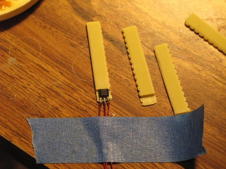
I've been working on adding the hall sensors to my motor, I'm putting six sensors in the back motor. I only expect to use 3 as per normal BLDC position feedback but I'm putting 3 more backup sensors in. I have heard they sometimes fail so this means if I do have a problem I can simply switch to the backup without having to teardown the motor to repair it.
I made 6 little pieces of fiberglass circuit board that fit snugly in the gaps in the motor stators, they have cutout pieces for the hall sensors, I'll glue the hall sensors to the fiberglass with polyester resin which I found out is used in the fabrication of the winding parts of AC induction motors. If it is suitable for this then it should be good for my motor too, its cheap and easy to use.
I stacked the motors together and took a photograph, I had to remove the plastic protection guard from the bottom motor as they would not fit with it in place.

 I had my first quote back from one machine shop and I'm awaiting more, it will be 4-5 weeks before I actually have machined parts in my hands ready to assemble, so plenty of time to finish other tasks.
I made 6 little pieces of fiberglass circuit board that fit snugly in the gaps in the motor stators, they have cutout pieces for the hall sensors, I'll glue the hall sensors to the fiberglass with polyester resin which I found out is used in the fabrication of the winding parts of AC induction motors. If it is suitable for this then it should be good for my motor too, its cheap and easy to use.
I stacked the motors together and took a photograph, I had to remove the plastic protection guard from the bottom motor as they would not fit with it in place.

Monday, November 22, 2010
Drawings finished....
So finally after a couple of months my drawings are finished enough for quotes from machine shops. Since sending them out I found a couple of missing dims and one dim I had to change but these won't change the quotes themselves.
I have sent them out to places all over to try and get the best price. This can be risky in that I don't know the reputation of some of the places but I'm hopeful it will work out ok.
It will take a couple more weeks to decide on a shop and once I give the go ahead a few more weeks at least waiting for parts to be finished.
I have other work to do while I'm waiting, embedding hall and temp sensors in the stators and prepping other parts. I've also been looking around for some old used car batteries cheap to test my electronics out, its proven to be difficult as even old virtually dead batteries have value for recycling.
I have sent them out to places all over to try and get the best price. This can be risky in that I don't know the reputation of some of the places but I'm hopeful it will work out ok.
It will take a couple more weeks to decide on a shop and once I give the go ahead a few more weeks at least waiting for parts to be finished.
I have other work to do while I'm waiting, embedding hall and temp sensors in the stators and prepping other parts. I've also been looking around for some old used car batteries cheap to test my electronics out, its proven to be difficult as even old virtually dead batteries have value for recycling.
Tuesday, November 9, 2010
Thanks to Tom Staub at High Plains Tool and Mold
My local machine shop didn't have the right tools to measure the stator dowel hole locations properly; so after some searching I found a website where some guys built a Honda Insight with a Tdi lupo engine. They had an adapter plate machined and so must have measured the dimensions I required.
Tom Staub at High Plains Tool and Mold (ph: 303-806-0451, 3201 S Zuni St # C Sheridan, CO 80110-1996) was happy to help and went to the trouble of finding his notes on the adapter plate. Thanks Tom!
Now I can proceed with finishing my drawings.
Tom Staub at High Plains Tool and Mold (ph: 303-806-0451, 3201 S Zuni St # C Sheridan, CO 80110-1996) was happy to help and went to the trouble of finding his notes on the adapter plate. Thanks Tom!
Now I can proceed with finishing my drawings.
Thursday, October 28, 2010
Design almost finished
I've made a lot of changes to the design, I managed to eliminate one part to save costs and simplify some of the others.
 I have a small amount of CAD work to finish off and then tidy up the drawings and tolerances. I have one motor at a machine shop which is being measured to check my dims.

Monday, October 18, 2010
Both motors have cooling tubes

Thursday, October 14, 2010


Sunday, October 10, 2010
One motor almost finished
Mixed 7oz of silicon RTV with 1lb of iron filiings, it mixed in quite easily. Used latex gloves and applied it to the pre-formed copper tubing wrapped around the stator. I had previously machined in clearance on various places using a dremel etc.
It was tricky to do but I have it finished, I used two zip ties at the tube outlets to hold them in place before adding a lot of pure silicon to prevent the tubes moving around.


It was tricky to do but I have it finished, I used two zip ties at the tube outlets to hold them in place before adding a lot of pure silicon to prevent the tubes moving around.


Friday, October 1, 2010
Heat
I have decided to water cool my stators in the motors; they are not designed for continuous use in the honda cars so they may get too hot in my EV.
I'm going to use a double wrap of 1/4" copper tubing with an ethylene glycol and water mix pumped with a home computer water cooling pump; the pump will flow around 1 gallon per minute at its maximum output.
There are two places I can add the copper, I can try and cool the copper coils themselves which is where the heat is generated or the outside of the stator assembly itself. I considered trying to cool the coils but I'm afraid whatever solution I come up with is going to risk damaging the coils, even if I get everything mounted ok its possible the tubes may rub and vibrate and wear through the insulation and create a short over time.
I'm going to wrap the outside of the stator assembly instead, I was going to purchase thermal insulation gasket material but its too expensive in the quantities I need for my EV ($300) so instead I'll either silicon them in place or epoxy.
To increase the thermal conductivity of the silicon/epoxy it would be nice to load it with particles that are highly thermally conductive, powdered copper or aluminum would be best but might be tricky to find or be too expensive. I'm considering using talcum powder instead which is magnesium silicate. I found a lot of data on talcum powder and I never knew it was actually a carcinogen, if I use this I'll be taking care to avoid handling it or breathing it in.
Edit: I found iron filings are cheaply available and only cost around $5 a pound, they are also non toxic and should be easier to mix with epoxy or silicone. I bought 3lbs online and they should arrive next week.
I'm going to use a double wrap of 1/4" copper tubing with an ethylene glycol and water mix pumped with a home computer water cooling pump; the pump will flow around 1 gallon per minute at its maximum output.
There are two places I can add the copper, I can try and cool the copper coils themselves which is where the heat is generated or the outside of the stator assembly itself. I considered trying to cool the coils but I'm afraid whatever solution I come up with is going to risk damaging the coils, even if I get everything mounted ok its possible the tubes may rub and vibrate and wear through the insulation and create a short over time.
I'm going to wrap the outside of the stator assembly instead, I was going to purchase thermal insulation gasket material but its too expensive in the quantities I need for my EV ($300) so instead I'll either silicon them in place or epoxy.
To increase the thermal conductivity of the silicon/epoxy it would be nice to load it with particles that are highly thermally conductive, powdered copper or aluminum would be best but might be tricky to find or be too expensive. I'm considering using talcum powder instead which is magnesium silicate. I found a lot of data on talcum powder and I never knew it was actually a carcinogen, if I use this I'll be taking care to avoid handling it or breathing it in.
Edit: I found iron filings are cheaply available and only cost around $5 a pound, they are also non toxic and should be easier to mix with epoxy or silicone. I bought 3lbs online and they should arrive next week.
Monday, September 27, 2010
Microcontroller
I have been researching what kind of microcontroller systemt to purchase to control the MDM. I did find some powerful but inexpensive ones such as the leaflabs maple:
leaflabs maple
Which has a 72Mhz 90MIPS processor (complex motor control needs about 12-25 MIPS) that uses an open source version of C that is easy to program in. However I would have to write the code for it basically from scratch, this would be a lot of work so I decided to purchase something with more support for motor control with some pre-written library files. I got a microchip evaluation board for BLDC motor control, I also bought an inexpensive BLDC 3 phase motor with built in hall sensors from ebay. I plan on setting up the board with the small motor and getting all the software working, then bypass the mosfet state in the board and drive the honda MDM directly.
 microchip
leaflabs maple
Which has a 72Mhz 90MIPS processor (complex motor control needs about 12-25 MIPS) that uses an open source version of C that is easy to program in. However I would have to write the code for it basically from scratch, this would be a lot of work so I decided to purchase something with more support for motor control with some pre-written library files. I got a microchip evaluation board for BLDC motor control, I also bought an inexpensive BLDC 3 phase motor with built in hall sensors from ebay. I plan on setting up the board with the small motor and getting all the software working, then bypass the mosfet state in the board and drive the honda MDM directly.
Thursday, September 23, 2010
MDM module wiring
With the Honda insight manuals in hand I went through the wiring to the MDM module this evening. I am 99% sure this is correct but I'll double check it before I apply power.
It looks fairly easy to hook up.

It looks fairly easy to hook up.

Wednesday, September 22, 2010

Parts arrive from ebay

Edit: the seller apologized and has apparently sent out a replacement motor unit, should arrive next week
Subscribe to:
Posts (Atom)